Create Piping and Instrumentation Diagrams (PIDs) of existing model files beginning with Pipe2018. The files lose none of their function and can be analyzed as a normal model. Choose from three different sizes of 2-D and three different sizes of 3-D symbols, called glyphs, to differentiate them from the normal, non-PID symbols.
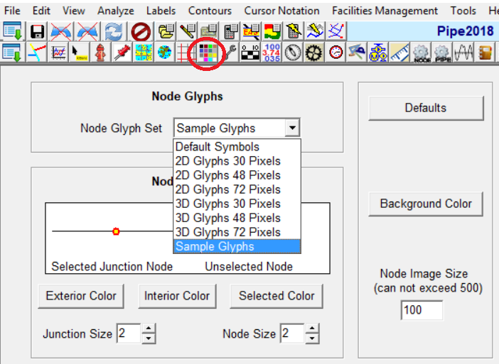
Select 2-D or 3-D Glyph Sizes within the Colors Menu
Once you have selected 2-D or 3-D glyphs, click on the Glyph Menu in the Node Info Window to change the glyph type and orientation.
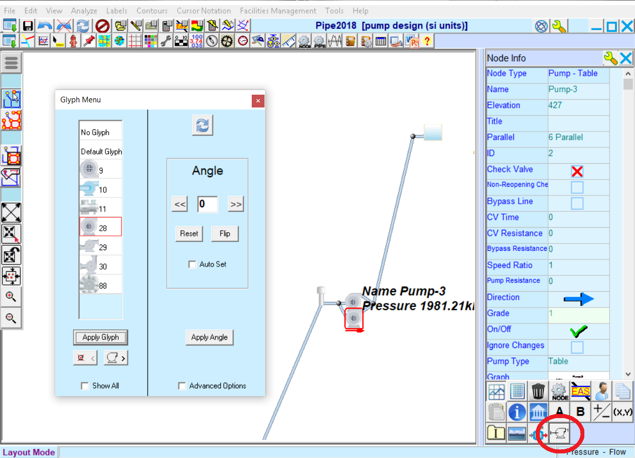
Glyph Menu Accessed from within the Node Info Window
Both 2-D and 3-D PIDs can be shown on a variety of backgrounds: this includes image files, internet background maps, CAD drawings, PDF drawings, or a grid. Pipe lengths can be fixed so PIDs drawn on a grid can be orthogonalized and thus mirror more traditional PID formats without losing functionality.
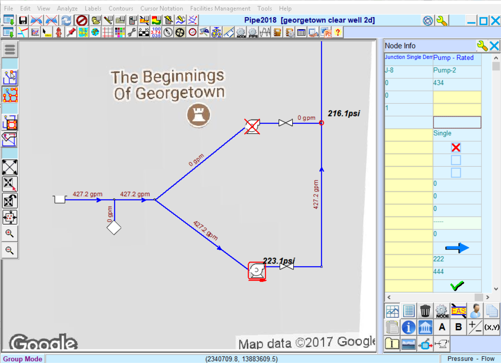
2-D Piping and Instrumentation Diagram on a Google Roadmap
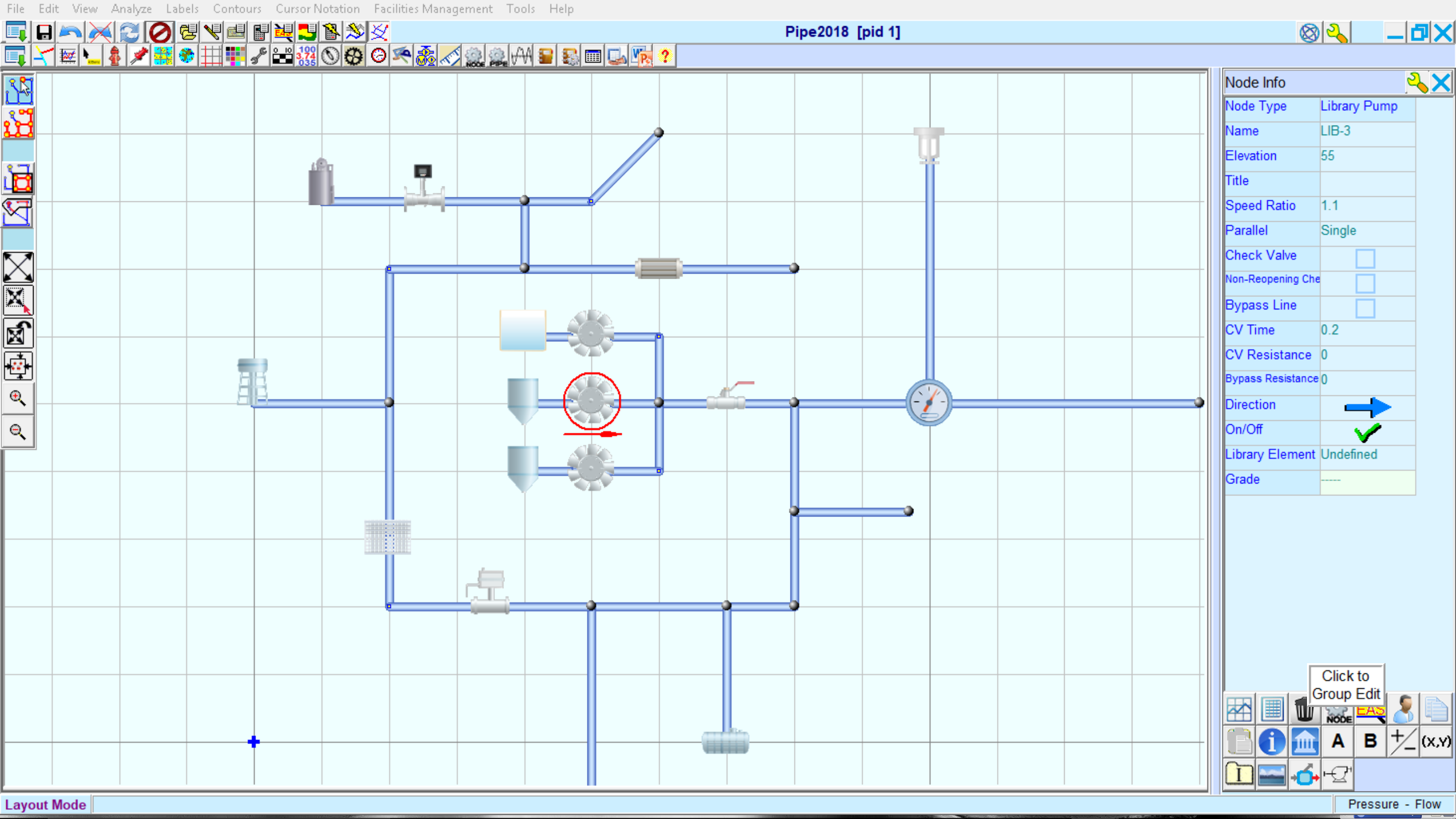
3-D Piping and Instrumentation Diagram on a Colored Grid

