NFPA Requirements Using KYPipe, GoFlow, and Surge
Hydraulic Calculations
KYPipe, GoFlow, and Surge meet the formula requirements for calculations as described in
NFPA 13 – 22.4.2
NFPA 15 – 8.5
NFPA 16 – 7.4
Analysis scenarios and conditions outlined in these standards may be created within KYPipe and GoFlow.
Surge is limited to basic steady state analysis. Surge specializes in unsteady flow analysis. Therefore KYPipe or GoFlow is required to carry out some specific steady analysis scenarios such as Required Capacity, Remote Location, and ESFR.
NPFA 13 and 15 Reporting with KYPipe and GoFlow
A sprinkler system is developed within KYPipe or GoFlow.
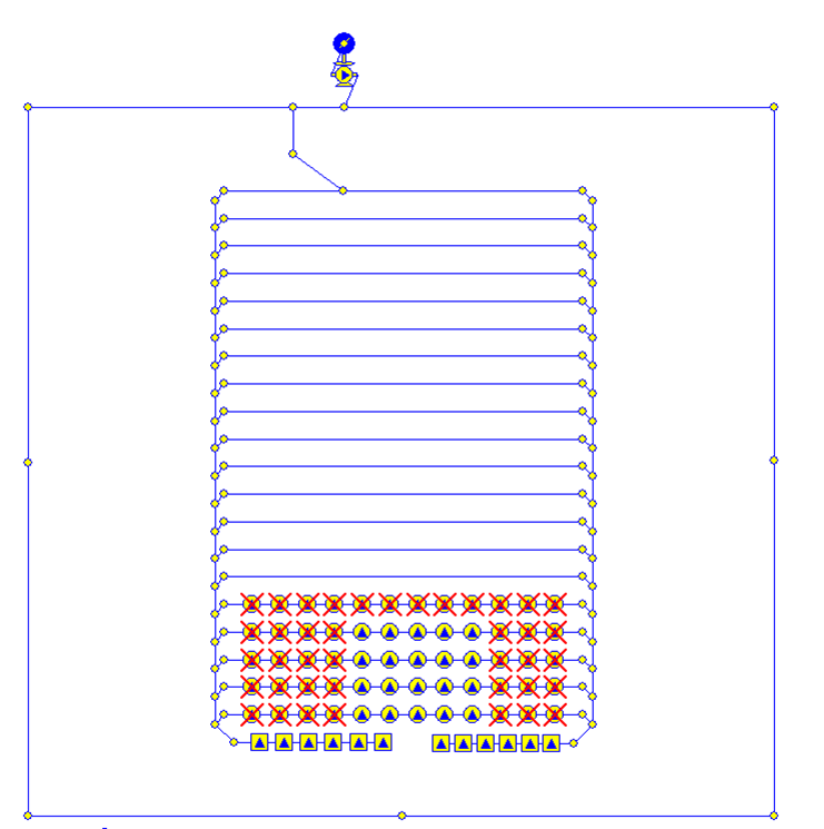
Sprinkler System Layout in KYPipe or GoFlow
Run an Analysis

Capacity Analysis for Sprinkler System
Required Capacity analysis produces information required for NFPA reporting.
NFPA 13 and 15 Reporting Features
After analysis has been completed, open Summary/Supply Plot feature.
Both program interfaces are shown.

Create a Summary Report and Supply Plot
Summary Sheet Requirements
- NPFA 13 22.3.2 Summary Sheet. The summary sheet shall contain the following information, where applicable:
- Date
- Location
- Name of owner and occupant
- Building number or other identification
- Description of hazard (for storage applications, the commodity classification, storage height, and rack configuration shall be included)
- Name and address of contractor or designer
- Name of approving agency
- System design requirements, as follows:
- (a) Design area of water application, ft 2 (m 2 )
- (b) Minimum rate of water application (density), gpm/ft 2 (mm/min). Where sprinklers are listed with minimum water application in gpm (L/min) or pressure in psi (bar), the minimum rate of water application shall be indicated in gpm (L/min) or pressure, psi (bar).
- (c) Area per sprinkler, ft 2 (m 2 )
- Total water requirements as calculated, including allowance for inside hose, outside hydrants, and water curtain and exposure sprinklers
- Allowance for in rack sprinklers, gpm (L/min)
- Limitations (dimension, flow, and pressure) on extended coverage or other listed special sprinklers
- NPFA 15 8.3.2 Summary Sheet. The summary sheet [for sample summary sheet, see Figure B.1(a)] shall contain all of the following information where applicable:
- The date
- The location
- The name of the owner and occupant
- The building or plant number
- The description of the hazard
- The name and address of the contractor and calculator
- The name of the authority having jurisdiction
- The design purpose
- The rates of the water application (density) and applied areas in gpm/ft2 [L/min)/m2]
- The total system water requirements as calculated, including allowance for hose streams
- The total designed water demand with number of systems designed to operate simultaneously at a reference point, preferably the source of supply, including hose streams and other fire protection equipment
- Water supply information

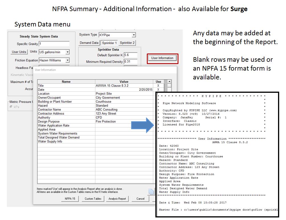
How Data for Summary Sheet is Input

Summary Sheet for NFPA 13 Items

Summary Sheet for NFPA 15 Items
Other Options for Input of Summary Sheet Items (Surge)
Detailed Worksheets
- NPFA 13 22.3.3 Detailed Worksheets. Detailed worksheets or computer printout sheets shall contain the following information:
- Sheet number
- Sprinkler description and discharge constant (K)
- Hydraulic reference points
- Flow in gpm (L/min)
- Pipe size
- Pipe lengths, center to center of fittings
- Equivalent pipe lengths for fittings and devices
- Friction loss in psi/ft (bar/m) of pipe
- Total friction loss between reference points
- Inrack sprinkler demand balanced to ceiling demand
- Elevation head in psi (bar) between reference points
- Required pressure in psi (bar) at each reference point
- Velocity pressure and normal pressure if included in calculations
- Notes to indicate starting points or reference to other sheets or to clarify data shown
- * Diagram to accompany gridded system calculations to indicate flow quantities and directions for lines with sprinklers operating in the remote area
- Combined Kfactor calculations for sprinklers on drops, armovers, or sprigs where calculations do not begin at the sprinkler
- NPFA 15 8.3.3 Detailed Worksheets. Detailed worksheets or computer printout sheets [for sample worksheet, see Figure B.1(b)] shall contain all of the following information:
- Sheet number, date, job number, and identification of calculations covered
- Description of discharge constant (K) (or provide the discharge curve or tabulation) for each nozzle type
- Hydraulic reference points
- Flow in gpm (L/min)
- Pipe size in in. (mm)
- Pipe lengths, center to center of fittings (or cut lengths) in ft (m)
- Equivalent pipe lengths for fittings and devices in ft (m)
- Friction loss in psi (bar) between reference points
- Total friction loss in psi (bar) between reference points
- Elevation head in psi (bar) between reference points
- Required pressure in psi (bar) at each reference point
- Velocity pressure and normal pressure if included in calculations
- Notes to indicate starting points, reference to other sheets, or to clarify data shown
- Combined K-factor calculations for nozzles on drops, armovers, or sprigs where calculations do not begin at a nozzle
- Where extending existing equipment, hydraulic calculations indicating the previous design, volume, and pressure at points of connection, and adequate additional calculations to indicate effect on existing systems
While some of the information will be provided by the consultant, many of these worksheets can be easily produced within the standard presentation capabilities of KYPipe and GoFlow.

NFPA Style Graph Sheet: Supply Plot
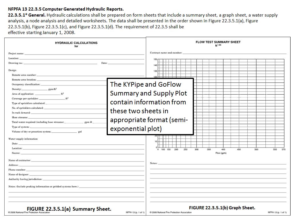
NFPA Computer Generated Hydraulic Report Requirements
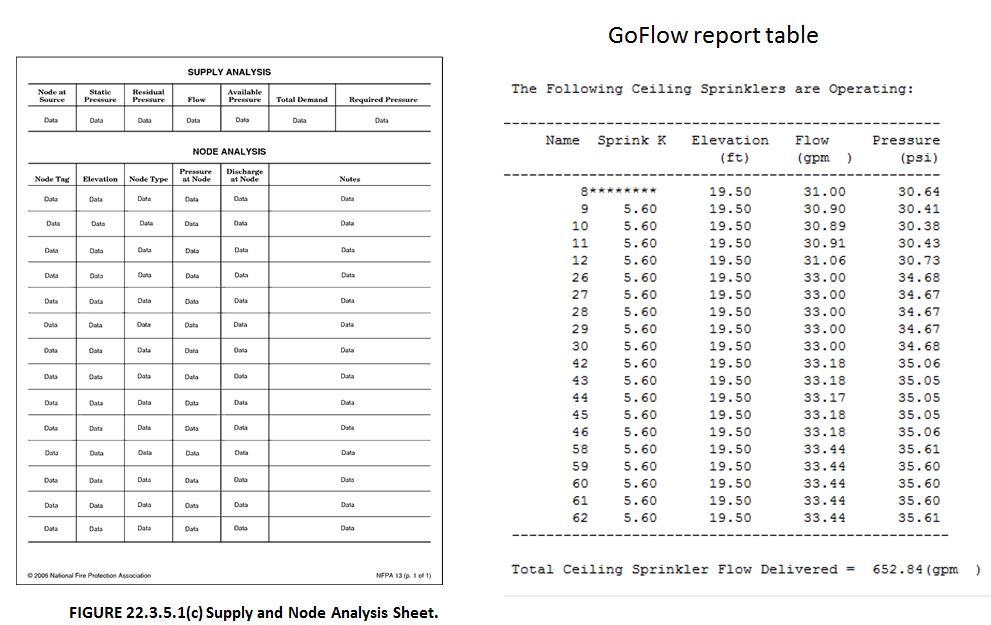
GoFlow Report Table Contains NFPA Supply and Node Analysis Sheet Data

GoFlow Report Contains Data from NFPA Detailed Work Sheet
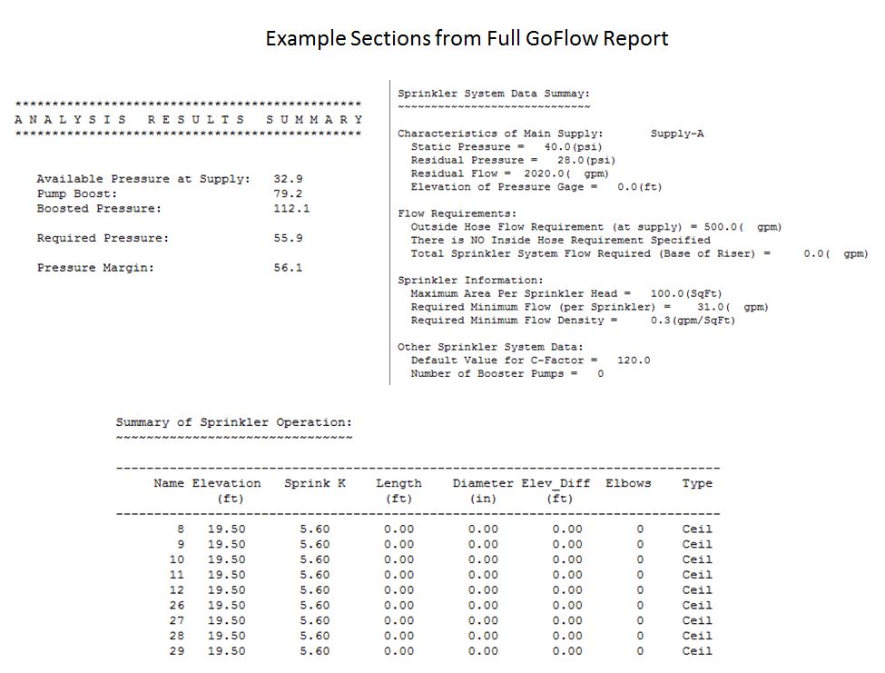
GoFlow Report Sections

GoFlow Report Sections Continued

