The Check Valve Animation Feature allows users to see a time-dependent display of a check valve’s position for any pump in the model. Additional outputs include flow, pressure and pump speed.
Users can select from three different types of check valves; swing-type, wafer-type, and axial. The check valve position is shown graphically, numerically and pictorially with the animation window. Users can thus see the check valve opening and closing in real time.
Here are the feature’s graphical outputs; see below for additional outputs (numerical and pictorial):
This is the Check Valve Animation Window. Below is a video describing the feature, as well as explanations for the various graphs and animations:
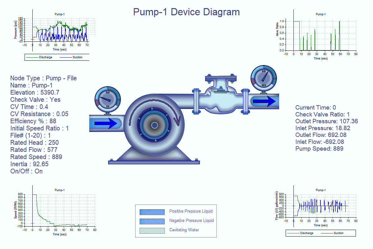
1. Check Valve Animation Window (CV Fully Open)
The position of the check valve is shown pictorially within the pump diagram, numerically and graphically. A check valve position of 1.0 is fully open, and a position of 0.0 is fully closed.
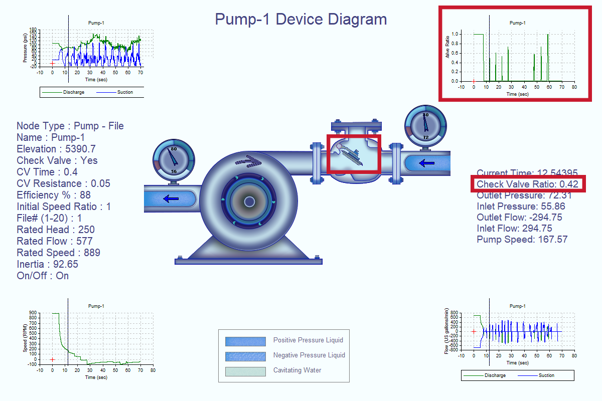
2. Check Valve Position
Inlet and outlet flows are displayed graphically, numerically and as animations using vector arrows within the pump’s inlet (suction) and outlet (discharge) pipes to differentiate between forward, zero or reverse flows. The sign convention for flows is (+) for flows leaving a device, and (-) for flows towards a device: the inlet flow in the image below is negative and the outlet flow is positive, which means both inlet and outlet flows are moving the same direction (left-to-right, in the direction of the pump’s rotation).
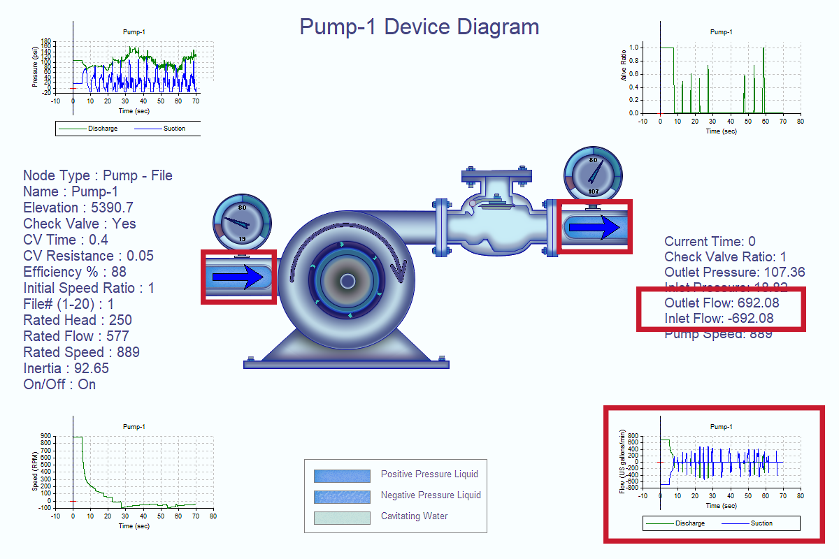
3. Pump Flow (Inlet/Outlet)
This feature also displays inlet and outlet pressures graphically, numerically and using needle gauges which display the inlet and outlet pressure range from cavitation up to the maximum pressure for the simulation.
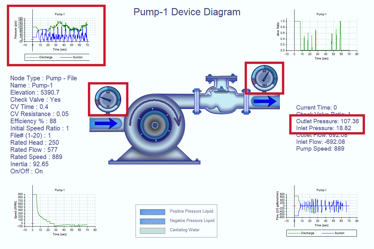
4. Pump Pressure (Inlet/Outlet)
The display of the water (or other liquid, for users modeling an incompressible fluid besides water) in the inlet and outlet pipes changes to show three conditions:
- Blue-colored water is water above atmospheric pressure.
- Blue-colored water with white bubbles shows water below atmospheric pressure but above cavitation pressure.
- White-colored water with blue bubbles shows cavitation.
Users can specify the cavitation pressure of the simulation.
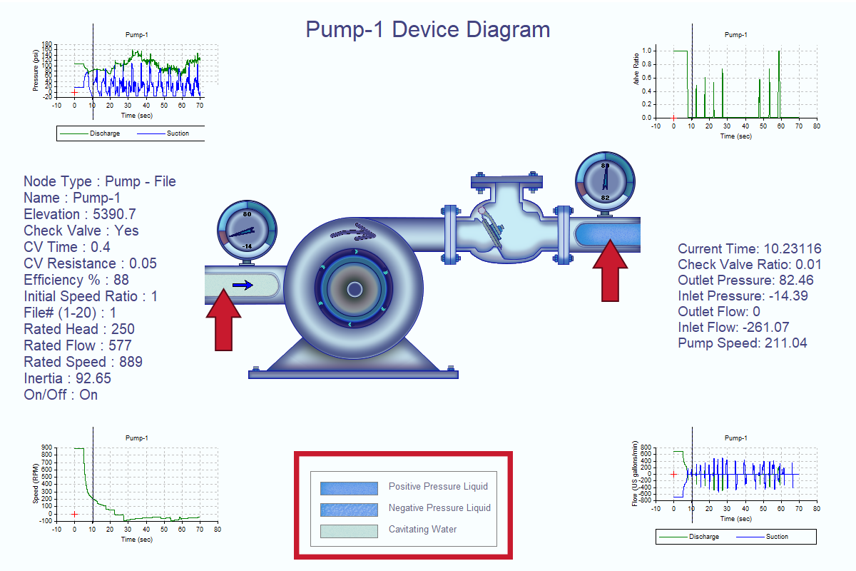
5. Water Pressure Divisions (Inlet/Outlet)
This feature is available in both KYPipe and Surge. Within Surge, the animation shows the check valve position at a model-defined time step. Within KYPipe, the check valve position can be displayed for each user-define time step (Extended Period Simulations, or EPS) or case (steady-state simulations). In Surge, the check valve ratio outputs can be used to determine the presence of check valve chatter: see Dr. Srinivasa Lingireddy’s blog post on non-reopening check valves for further information on check valve chatter.


