Chapter 1 – Wave Plan Method
Surge Analysis and the Wave Plan Method
Supplementary Material: Example Problems and Solutions
Chapter 1 – Problem 1.21
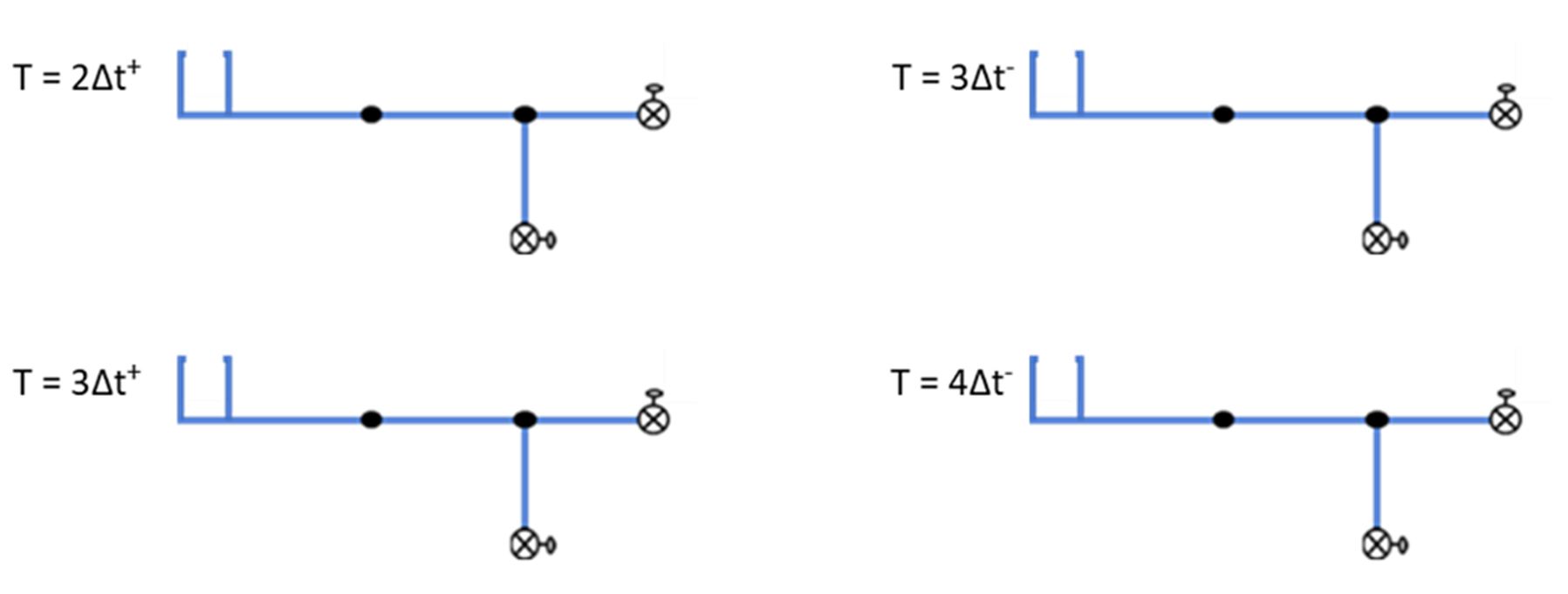
1.21 Consider a branch pipe network as shown in the following figure.

All pipe sections are of same length (L), diameter (D), and celerity values (c). The open valve on the branch line closes instantaneously at time 0 and generates a pressure wave of +9 bar. Track this pressure wave using WPM as it moves into the network and is reflected and transmitted at junctions and other boundary nodes. Use a computational time step of Δt = L/c and mark the pressure waves on the attached schematics for at least four computational time steps. Ignore friction.
Solution:
Sections 1.5 and 1.6 in the book “Surge Analysis and the Wave Plan Method” describe the wave action at junction nodes as well as reservoirs and dead ends. Equations 1.33 and 1.41 can be used to calculate the reflection and transmission coefficients. As all pipes meeting at the three-pipe junction node have identical characteristics, the transmission coefficient of T = 2/3, and the reflection coefficient of R = -1/3 apply to all incoming pressure waves irrespective of their associated pipe section. The following figure shows pressure waves at different computational time steps. Most of the numbers are self-explanatory. The superscript “–“ in t = Δt– indicates the time just prior to the wave(s) reaching the boundary, and the superscript “+” represents the time just after the wave action at the boundary.
At t = 3Δt+, the pressure wave of -3 bar approaching the junction node from Pipe-1 is reflected as R1 = (-1/3) * (-3) = +1 bar back into Pipe-1. This wave is also transmitted into Pipe-2 and Pipe-3 as T1 = (2/3) * (-3) = -2 bar. Likewise, the pressure wave of +6 bar approaching the junction node from Pipe-2 is reflected as R2 = (-1/3) * (+6) = -2 bar back into Pipe-2 and is transmitted into Pipe-1 and Pipe-3 as T2 = (2/3) * (+6) = +4 bar. As the waves are superimposed, the pressure wave that moves into Pipe-1 from the three-pipe junction node is T2+R1 = +5 bar. The pressure wave that moves into Pipe-2 from the three-pipe junction node is T1+R2 = -4 bar.


Summary of revisions to this page:
Date/Revision

